
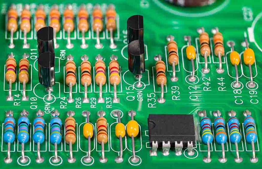
When you open an electronic device, you might come across numerous colours and markings on the circuit boards. Many colours are used to mark and differentiate various electronic components; both single and multiple colour combinations are applied. Let’s dive into the colourful world of colour codes in passive electronic elements.
Use of Color Codes
In small electronic parts, labelling names and values can be cumbersome. In order to avoid inconsistencies with size and legibility, colour codes are used to depict values and characteristics. The method is predominantly seen in passive electronic units like resistors, inductors, capacitors, etc.A different type of code, the 25-pair code, is employed to recognise wires in telecommunications cables.
International Electrotechnical Commission is the body that states and regulates standard colour coding parameters.
The total value of resistance, capacitance and inductance can be easily calculated using colour codes.
History of Color Codes
In the 1920s, the Color code was introduced by the Radio Manufacturers Association. Three-band codes were first applied to mark resistance values. The fourth band (for tolerance) was later added.
In the beginning, there were no separate bands for the three colours. In fact, there was nothing to represent neutral background colours. In 1952, the International Electrotechnical Commission started to standardise colour codes across all electronic components like capacitors, inductors, etc.
Reasons for the popularity of Colour Codes
Optimal readability is one of the important selling points of the colour code method.
Deciphering a complex combination of numerals is much more complicated than decoding a series of coloured bands marked around electronic components. It is challenging to read digits or numerals in dim and visually diluted conditions.
When mounted on a board, colour bands should be easily visible from every possible viewing angle ( as plain colours do not have orientation issues).
In the case of numeric symbols, as numbers are sensitive to orientation, they might be visually confusing.
Production cost is another deciding factor. In large scale productions, marking numbers is much more laborious than printing colour bands on small cylinders.
Important electronic components with Colour Codes
Colour-coded resistors are commonly used everywhere. They consist of various colour bands ciphering resistance values, and encoding tolerance values.
With the help of the resistance colour code, we can easily deduce the value and tolerance of the given resistance.
The values are always noted in Ohms. The tolerance band is usually isolated by a notable gap, while colour bands expressing a resistance value are kept close together.
The two major colour codes are five-colour codes and four-colour codes.
Coloured capacitors are not as standard as coloured resistors or inductors. They can be labelled with four or more coloured rings or dots. It was pretty common back in the days, but it seems manufacturers are moving away from this practice.
They are occasionally coloured, and their units are picofarads. The colours usually encode the first and second most relevant numbers of the value (picofarads). The third colour shows the decimal multiplier. Supplementary bands have different meanings depending on the types of capacitors.
Coloured cylindrical capacitors may visually resemble resistors.
- Small inductors are labelled using resistor colour code. Inductance is generally noted in microhenries.
The mantissa is encoded using two colour-coded digits, and one colour code is used to cypher the multiplier.
Takeaways from Color Coding Method
As mentioned earlier, colour bands are widely used because they are cheaply and easily printable on any tiny component. However, the major drawback is colour blind people cannot use colour as reference points.
In other cases, excessive heating of components or contamination may result in discolouration. It may become impossible to differentiate orange from brown, vice versa. Besides some of these drawbacks, still, colour coding is the most reliable and consistent method available at present. Ultimately they are straightforward to read, and the position or orientation of the resistor doesn’t matter.